
Magnetic circuit
The reluctance motor
Advantages of the reluctance motor:
- no permanent magnet
- consists mostly of soft iron and wiring
- simple mechanics
- also efficient at high speed
- only limited by the electrical power source and electrical switching speed
Disadvantages of the reluctance motor:
- Advanced electronics
- Requires current sensors and position sensor
Magnetic circuits
Physical laws
Definitions:
- : magnetomotive force (unit: )
- : magnetic flux (unit: or or )
- : reluctance (unit: or )
- : number of wire loops
- : electric current in one wire loops (unit: )
- : length of the magnetic circuit (unit: )
- : area of a section of the magnetic circuit (unit: )
- : magnetizing field (unit: )
- : magnetic flux density (unit: or )
- : magnetic permeability (unit: or )
- : vacuum magnetic permeability :
Laws at macroscopic scale (from integral equations):
Laws at microscopic scale (from differential equations):
Energy:
- : magnetic energy density (unit: or )
- : energy of a magnetic circuit (unit: or )
Electrical circuit:
- : electromotive force of a turn (unit: or )
- : electromotive force of the winding (unit: or )
- : inductance of a solenoid (unit: or )
- if constant over time
- Let's define
Regular torus
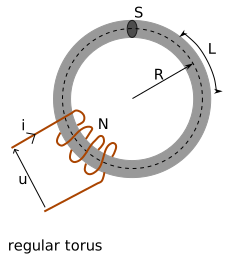
- (length of the torus)
| Material | Relative permeability |
|---|---|
| Air | 1 |
| Iron 99.95 | 200 000 |
| Iron 99.8 | 5000 |
| Soft iron | 5000 |
| Cobalt | 250 |
| Nickel | 600 |
| Cobalt-iron | 18000 |
| Mu-matierial | 50 000 |
| Permalloy (nickel-iron) | 1000 000 |
| Symbol | Parameter | Value | |
|---|---|---|---|
| Relative permeability | |||
| R | Torus radius (mm) | ||
| Torus section area () | |||
| Number of turns | |||
| Current in the winding (A) | |||
| Torus length (mm) | 94.2 mm | ||
| Magnetomotive force (A) | 6.000e+3 A | ||
| Reluctance () | 1.500e+5 | ||
| Magnetic flux () | 4.000e-2 H.A | ||
| Magnetic field () | 4.000e+2 T | ||
| Magnetic energy () | 1.200e+2 J | ||
| Inductance () | 1.067e+2 H |
Torus with swelling
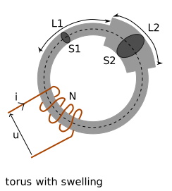
| Symbol | Parameter | Value | |
|---|---|---|---|
| Percentage of torus with L2 (%) | |||
| Percentage of S2 compare to S1 (%) | |||
| Length of L1 () | 66.0 mm | ||
| Area of S1 () | 100.0 | ||
| Length of L2 () | 28.3 mm | ||
| Area of S2 () | 200.0 | ||
| Magnetomotive force (A) | 6.000e+3 A | ||
| Reluctance () | 1.275e+5 | ||
| Magnetic flux () | 4.706e-2 H.A | ||
| Magnetic field () | 4.706e+2 T | ||
| Magnetic field () | 2.353e+2 T | ||
| Magnetic energy () | 1.412e+2 J | ||
| Inductance () | 1.255e+2 H |
Torus with air gap
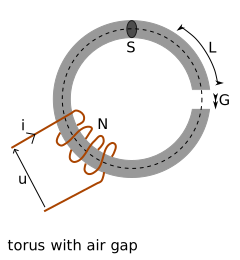
| Symbol | Parameter | Value | |
|---|---|---|---|
| The thickness of air-gap () | |||
| Magnetomotive force (A) | 6.000e+3 A | ||
| Reluctance () | 8.108e+6 | ||
| Magnetic flux () | 7.400e-4 H.A | ||
| Magnetic field () | 7.400e+0 T | ||
| Magnetic field () | 7.400e+0 T | ||
| Magnetic energy () | 2.220e+0 J | ||
| Inductance () | 1.973e+0 H |
Torus with shuttle
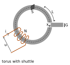
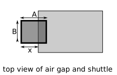
| Symbol | Parameter | Value | |
|---|---|---|---|
| Relative permeability of the shuttle | |||
| Length of the air-gap () | |||
| Width of the air-gap () | |||
| Shuttle position (%) | |||
| Torus section area () | 100.0 | ||
| Air area () | 50.0 | ||
| Shuttle area () | 50.0 | ||
| Magnetomotive force (A) | 6.000e+3 A | ||
| Reluctance () | 1.532e+5 | ||
| Magnetic flux () | 3.917e-2 H.A | ||
| Magnetic field in torus () | 3.917e+2 T | ||
| Magnetic field in air-gap () | 3.917e+2 T | ||
| Magnetic field in shuttle () | 3.917e+2 T | ||
| Magnetic energy () | 3.168e+3 J | ||
| Inductance () | 1.045e+2 H | ||
| Force () | 5.840e+1 N |
Torus with realistic shuttle
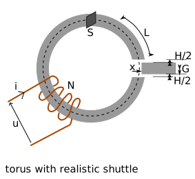
| Symbol | Parameter | Value | |
|---|---|---|---|
| Thickness of slack () | |||
| Shuttle position (%) | |||
| Magnetomotive force (A) | 6.000e+3 A | ||
| Reluctance () | 1.745e+6 | ||
| Magnetic flux () | 3.439e-3 H.A | ||
| Magnetic field in torus () | 3.439e+1 T | ||
| Magnetic energy () | 3.383e+1 J | ||
| Inductance () | 3.007e+1 H | ||
| Force () | 4.680e-1 N |